Camera Solver (Backplates)
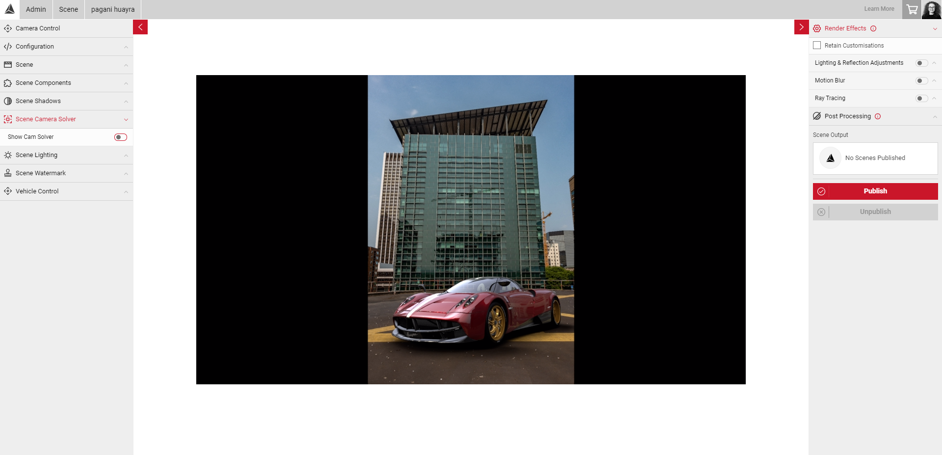
Note: After uploading your assets, you may notice back panels on either side of your image. This is due to the backplate respecting the aspect ratio of the source texture. This will also be visible in any rendered images from Shutter Pro.

As Backplates are 2D environments, users cannot move the camera around the scene. To help create a realistic linear perspective with the vehicle in the scene, the Camera Solver tool allows users to project the vanishing points by positioning the camera projection lines with geometry in the image.
The vanishing point is the point in the distance where parallel lines converge on the horizon line (eye level, or the height of the camera in an image).
Based on the geometry you have in your image, you can select the appropriate number of vanishing points to project which will generate the camera projection lines in the Viewport. You can then position these lines on the relevant axis by clicking and dragging the lines in the Viewport, to create a realistic sense of depth. You can select one, two or three vanishing points (one, two or three point perspective).
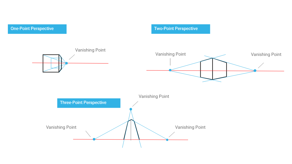
In one point perspective, all lines disappear into one point in the image, for example, this point is often located in the middle of the image/environment but can be anywhere. So should be used for environments with little to no hard geometry in the scene. For example, a straight road, a single room etc.
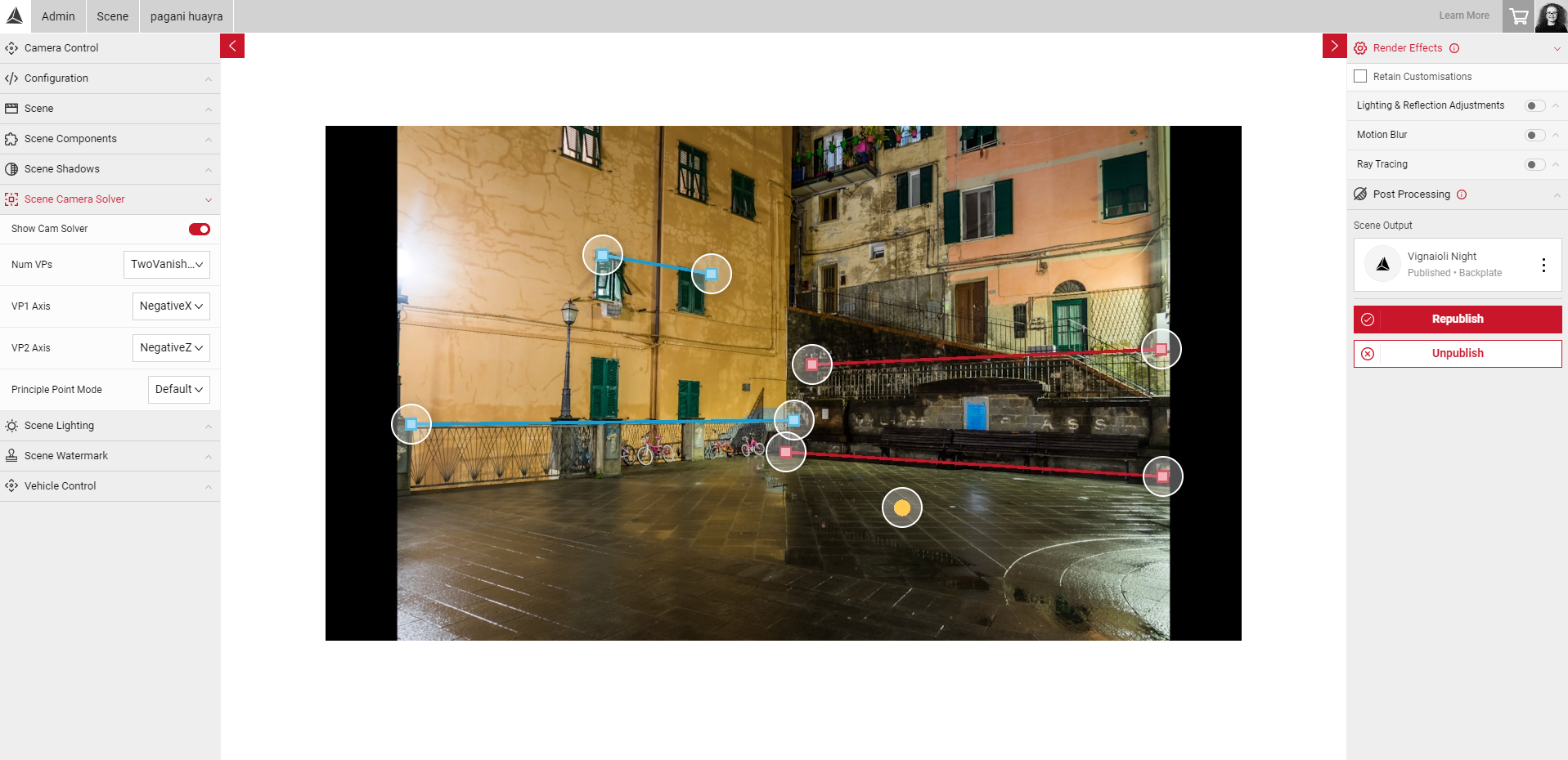
In two point perspective, all lines vanish into two points of the same height at the border of the image. All the vertical lines are perpendicular to the horizon, so this method should be used for environments including lots of geometry, such as a city scene with multiple buildings in view.
In third point perspective, all lines vanish into three points, where the camera appears to be above or below the horizon line. This method should be used for environments where the camera is in a low/high position.
One Vanishing Point
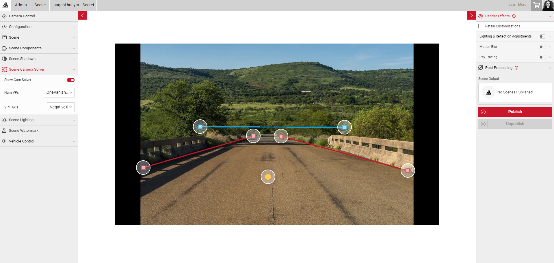
The One Vanishing Point option should be used for environments such as a straight road, where all VP lines would meet at one point on the horizon line and geometric shapes in the scene are "flat". After enabling the Camera Guides slider, you will see 3 VP projection lines in the Viewport, and a yellow dot which represents the world origin point. This point determines where the car is located in the 3D space, and can be dragged to change the position of the car once the projection lines are in the correct position.
- In this example, the road in the scene would eventually vanish into one point on the horizon line.
- The blue line represents the horizon line (height of the camera).
- The red lines represent the X axis, so these lines were positioned on each side of the road to project the vanishing point.
- With the vehicle enabled, we can see it is placed in a reasonable position in the scene, so we can then use the Vehicle Control settings to make finer adjustments to the car position and rotation.
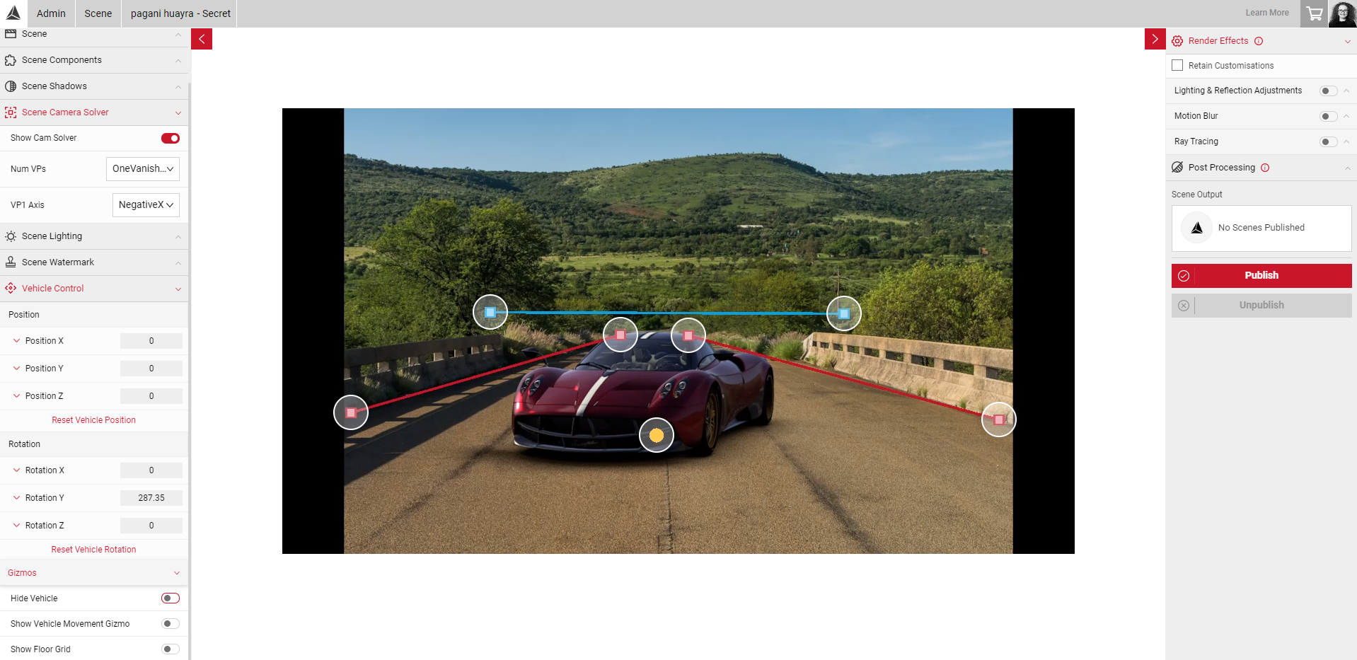
The colour of the projection lines use default colours to represent each axis, Red = X, Blue = Z, and Green = Y.
Two Vanishing Points
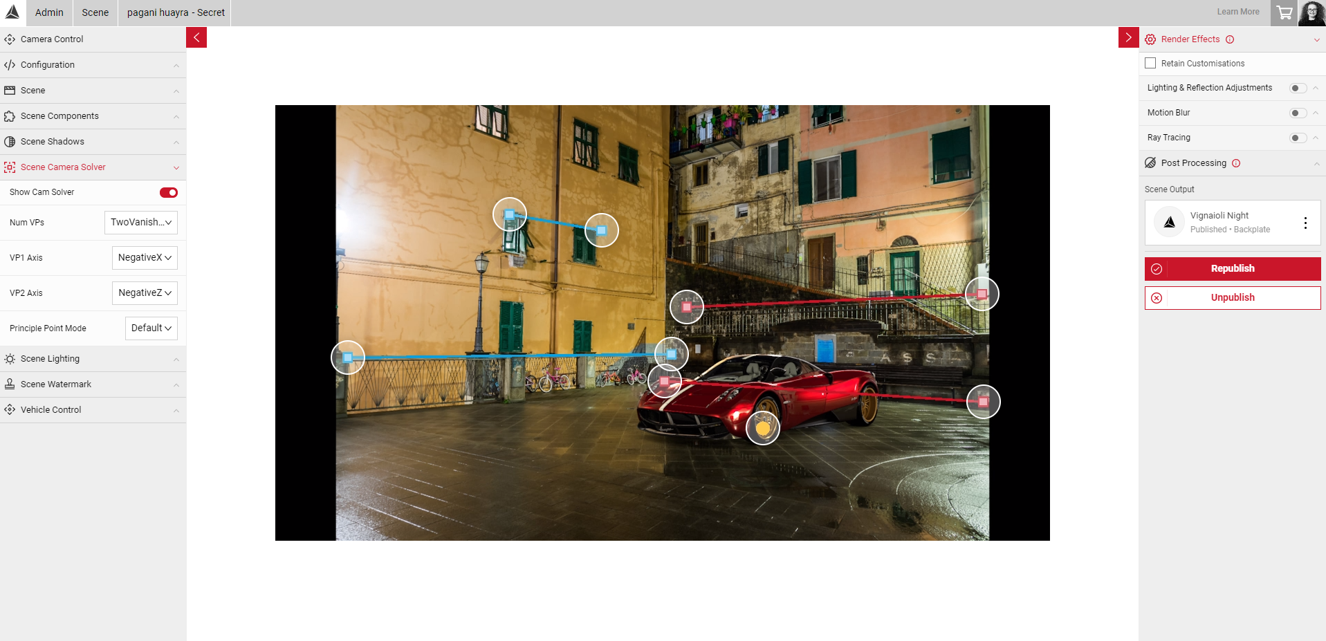
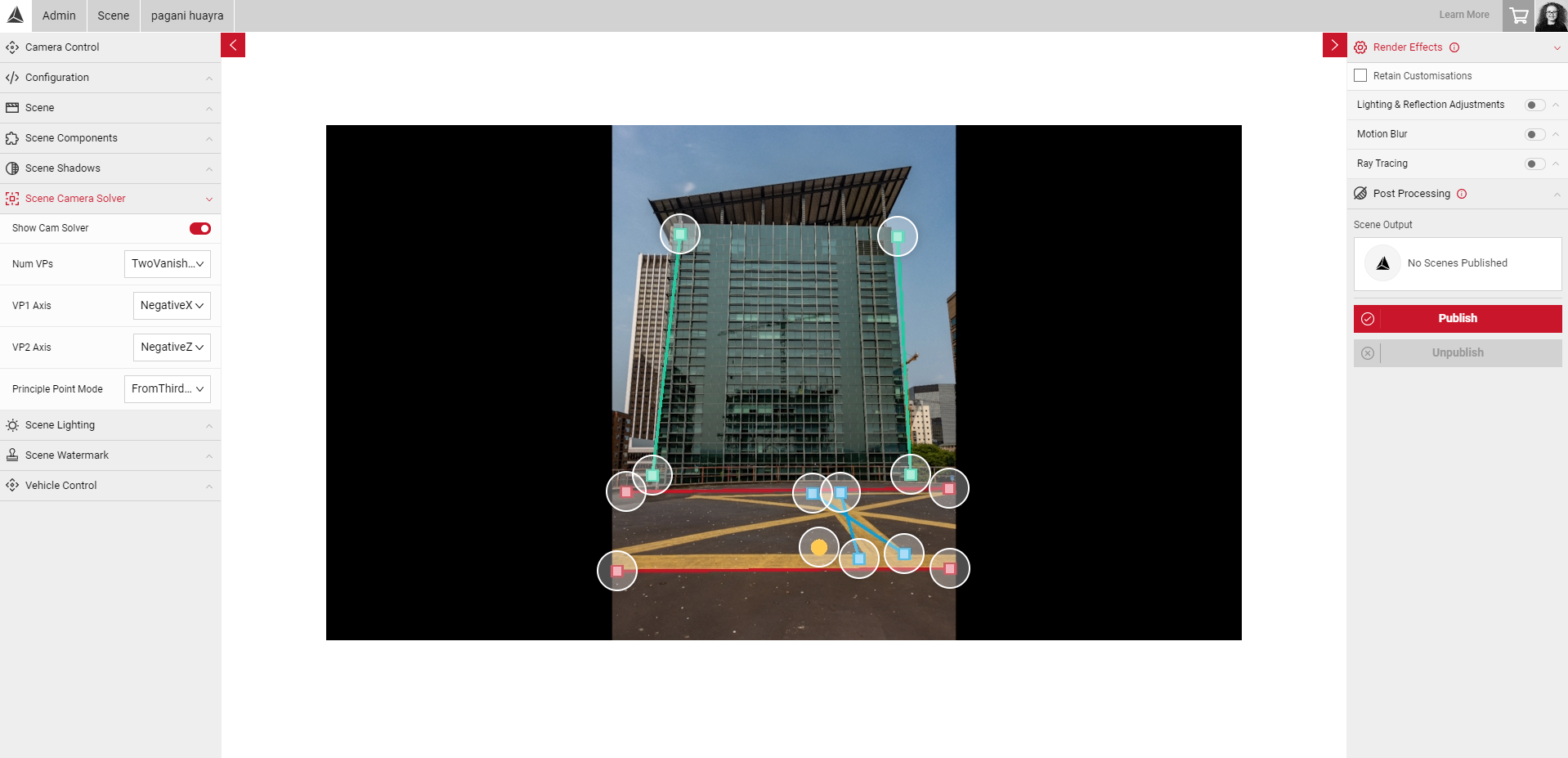
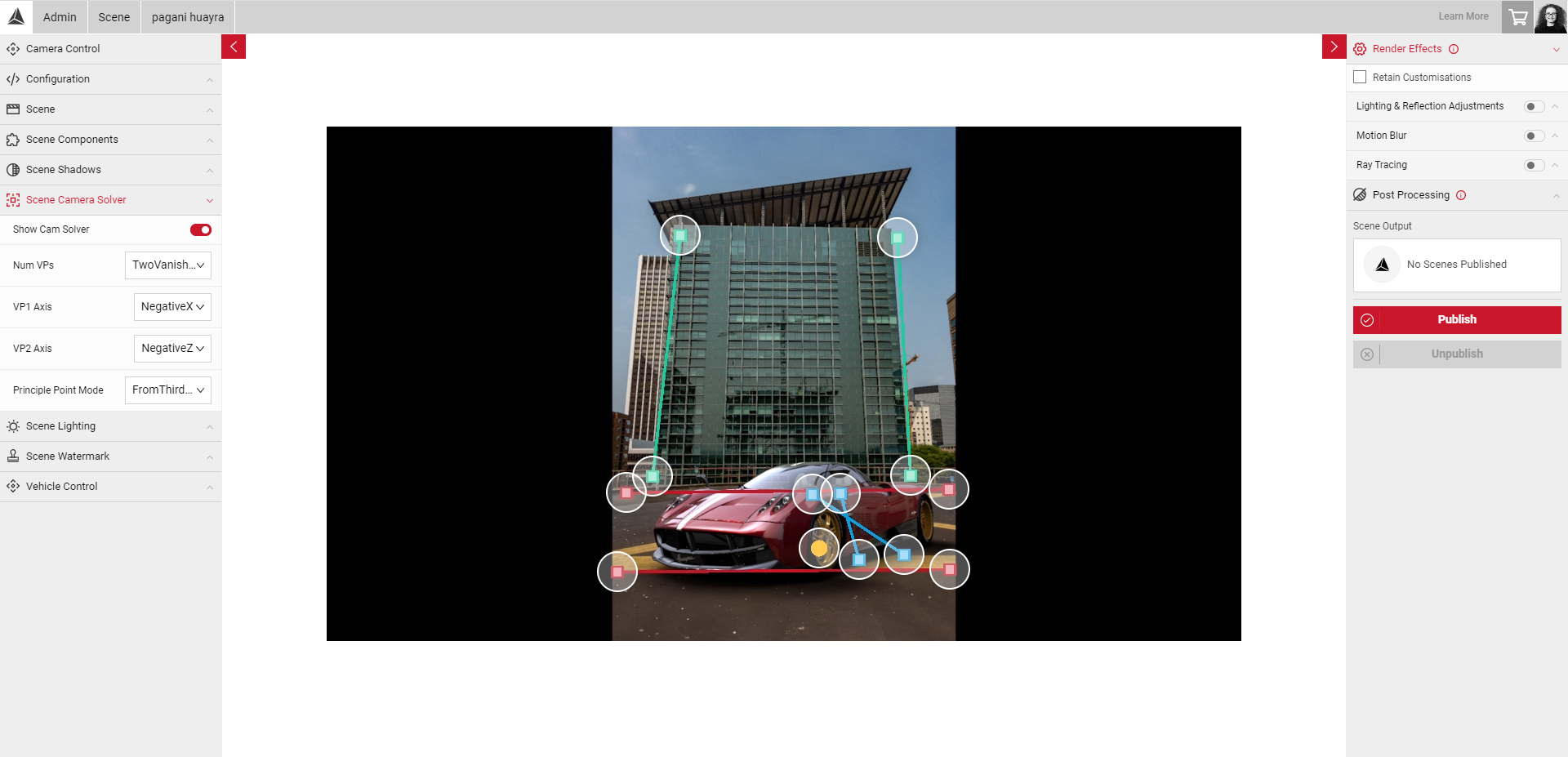
The Two Vanishing Point option should be used for environments including lots of geometry, such as a city scene with multiple buildings in view.
- In this example, we can see the vanishing points would disappear into two points, here we can position the projection lines on the X and Z axis to project where the vanishing points would be.
- You can also change the axis of each vanishing point to achieve the correct orientation. For example, if the car appears upside down, the axis could be changed from NegativeX to PositiveX which would change the vehicle to the correct orientation.
Third Vanishing Point
The Third Vanishing Point option should be used where all projection lines in the scene vanish into three points, where the camera appears to be above or below the horizon line.
- In this example, we can see the camera appears to be in a low position, below the horizon line.
- To enable the third vanishing point, select 2 vanishing points, and change the Principle Point Mode to From Third Vanishing Point.
- The projection lines for the Y axis (green lines) will then appear in the viewport.
- Now, we can position the projection lines along the X, Z and Y axis to align with the geometry in the image.
Setting Your Projection Lines
You can set the projection lines by clicking and dragging each line point to change the position. The positions you set here will be saved each time you load your scene.
Note: The vehicle is not specific to the Scene project and is not saved per Scene. All the same settings will be saved each time a different vehicle is selected, but vehicle position and lighting may appear differently.
- In the Camera Solver menu, select the Show Camera Guides slider.
- Establish the number of vanishing points your scene might have.
- Select the appropriate number in the Camera Solver menu.
- Click and drag each line point to project the vanishing points, making sure to align with the geometry. You will notice as you change the position of the lines, the car position in the 3D space will also move. It may be useful to hide the vehicle while setting your projection lines so the car doesn't obscure your view of the scene. You can do this by enabling the Hide Vehicle slider in the Vehicle Control menu.
- Then, deselect the Hide Vehicle slider to double check the position is correct.
- Next, change the polarity of each axis (if neccessary, for example if the car is upside down).
- Drag the world origin point (yellow dot) to move the vehicle to a suitable position and height. You can also enable the Floor Grid slider in the Vehicle Control menu to get the size reference and ensure the position is correct. The grid is 1m x 1m, and will shift position whenever the world origin point is moved.
Note: If you move the world origin point and nothing changes, this is due to an invalid projection. Try readjusting your VP lines to get the correct projection.
When you are happy with your vehicle position, you can make finer adjustment to the position and rotation by using the Vehicle Control tools. Then you can start to configure your Scene Lighting and Scene Shadows settings.